

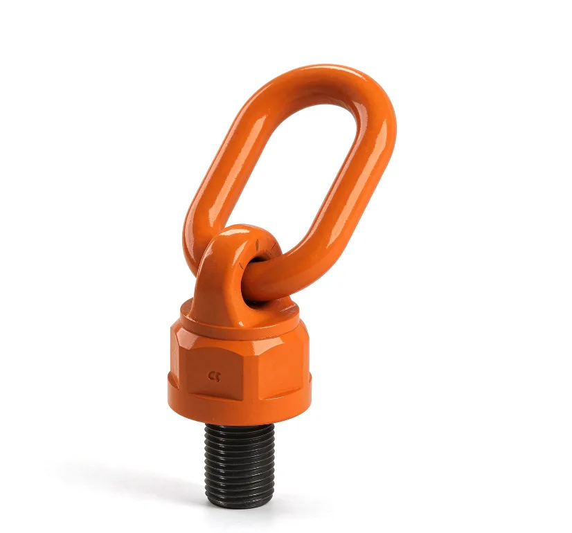
Swivel Hoist Ring
A reusable lifting point that screws into a threaded lifting socket or a tapped hole. An integrated ball bearing lets the hoist ring turn a full 360° under load while the ring pivots to follow the sling, so the thread is pulled in line. 26 sizes from M8 to M60, working load limit 0.4 to 20 t, safety factor 4:1.
Where it's used
Turning and Tilting Precast Elements
The hoist ring turns 360° and its ring pivots towards the sling, so wall panels and other elements can be turned or tilted up without bending the thread sideways.
Lifting from Threaded Sockets
Screws into cast-in threaded lifting sockets with a matching metric thread for demoulding, yard handling and loading elements onto trucks.
Moulds, Formwork and Plant Equipment
Bolts into tapped holes on steel moulds, formwork parts and machinery, giving a quick, reusable lifting point in the precast plant.
About the Swivel Hoist Ring
The GPS Swivel Hoist Ring (code GPS3801), also known as a swivel lifting eye, swivel lifting point or rotating lifting eye, is a reusable lifting point for precast concrete elements, moulds and equipment. It screws into a cast-in threaded lifting socket or a tapped hole with a matching metric thread.
An integrated ball bearing lets the hoist ring turn a full 360° under load, and the lifting ring pivots to line up with the direction of the sling. Because the hoist ring follows the pull, the thread is loaded in line instead of being bent sideways. This makes it a good choice for angled lifts and for turning or tilting elements.
The range covers 26 sizes from M8 to M60, with working load limits from 0.4 t to 20 t and a safety factor of 4:1. Each size has a recommended tightening torque, listed in the size table. The capacity of the complete lifting point also depends on the socket or tapped hole it is screwed into.
Thread length and thread specification can be customised on request.
Available Sizes
| Code | WLL (t) | Thread M | E (mm) | A ±2 (mm) | B ±3 (mm) | C (mm) | D (mm) | K (mm) | G (mm) | F ±3 (mm) | Torque (Nm) |
|---|---|---|---|---|---|---|---|---|---|---|---|
| GPS3801-M8 | 0.4 | M8×1.25 | 12 | 30 | 43.5 | 54 | 12 | 37 | 40 | 97.5 | 10-40 |
| GPS3801-M10 | 0.6 | M10×1.5 | 19 | 30 | 43.5 | 54 | 12 | 37 | 40 | 97.5 | 10-40 |
| GPS3801-M12S | 0.7 | M12×1.75 | 19 | 30 | 43.5 | 54 | 12 | 37 | 40 | 97.5 | 15-40 |
| GPS3801-M14 | 1.25 | M14×2.0 | 31.8 | 30 | 43.5 | 54 | 12 | 37 | 40 | 97.5 | 30-100 |
| GPS3801-M16S | 1.5 | M16×2.0 | 31.8 | 30 | 43.5 | 54 | 12 | 37 | 40 | 97.5 | 45-130 |
| GPS3801-M12B | 1.05 | M12×1.75 | 19 | 34 | 54.5 | 78 | 16 | 54.5 | 59 | 133 | 15-40 |
| GPS3801-M16B | 1.9 | M16×2.0 | 30 | 34 | 54.5 | 78 | 16 | 54.5 | 59 | 133 | 45-130 |
| GPS3801-M18S | 1.9 | M18×2.5 | 30 | 34 | 54.5 | 78 | 16 | 54.5 | 59 | 133 | 100-170 |
| GPS3801-M20S | 2 | M20×2.5 | 30 | 34 | 54.5 | 78 | 16 | 54.5 | 59 | 133 | 100-170 |
| GPS3801-M22S | 2 | M22×2.5 | 30 | 34 | 54.5 | 78 | 16 | 54.5 | 59 | 133 | 100-170 |
| GPS3801-M24S | 3.15 | M24×3.0 | 30 | 34 | 54.5 | 78 | 16 | 54.5 | 59 | 133 | 190-280 |
| GPS3801-M18B | 2 | M18×2.5 | 38.1 | 40 | 67 | 93 | 20 | 64.5 | 70 | 160 | 100-170 |
| GPS3801-M20B | 2.5 | M20×2.5 | 38.1 | 40 | 67 | 93 | 20 | 64.5 | 70 | 160 | 100-170 |
| GPS3801-M22B | 2.5 | M22×2.5 | 38.1 | 40 | 67 | 93 | 20 | 64.5 | 70 | 160 | 100-170 |
| GPS3801-M24B | 4 | M24×3.0 | 38.1 | 40 | 67 | 93 | 20 | 64.5 | 70 | 160 | 190-280 |
| GPS3801-M27 | 4 | M27×3.0 | 38.1 | 40 | 67 | 93 | 20 | 64.5 | 70 | 160 | 250-500 |
| GPS3801-M30S | 5 | M30×3.5 | 35 | 40 | 67 | 93 | 20 | 64.5 | 70 | 160 | 270-600 |
| GPS3801-M30B | 6 | M30×3.5 | 50 | 51 | 95 | 111 | 22 | 74 | 79 | 206 | 270-600 |
| GPS3801-M33 | 7.5 | M33×3.5 | 50 | 51 | 95 | 111 | 22 | 74 | 79 | 206 | 270-600 |
| GPS3801-M36 | 10 | M36×4.0 | 54 | 51 | 95 | 111 | 22 | 74 | 79 | 206 | 270-600 |
| GPS3801-M39 | 10 | M39×4.0 | 58 | 51 | 95 | 111 | 22 | 74 | 79 | 206 | 350-800 |
| GPS3801-M42 | 13 | M42×4.5 | 63 | 65 | 108 | 122.5 | 26 | 85 | 93 | 231 | 350-800 |
| GPS3801-M45 | 13 | M45×4.5 | 68 | 65 | 108 | 122.5 | 26 | 85 | 93 | 231 | 350-800 |
| GPS3801-M48 | 14 | M48×5.0 | 68 | 65 | 108 | 122.5 | 26 | 85 | 93 | 231 | 350-800 |
| GPS3801-M56 | 20 | M56×5.5 | 84 | 70 | 120 | 158 | 32 | 95 | 105 | 278 | 350-900 |
| GPS3801-M60 | 20 | M60×5.5 | 90 | 70 | 120 | 158 | 32 | 95 | 105 | 278 | 350-900 |
- Safety factor is 4:1
- Thread length and thread specifications can be customised on request
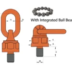
- Dimensions in mm; see the dimension drawing for the position of A to M
Related Products
Magnetic Steel Plates
View product
Flat Plate Lifting Socket
View product